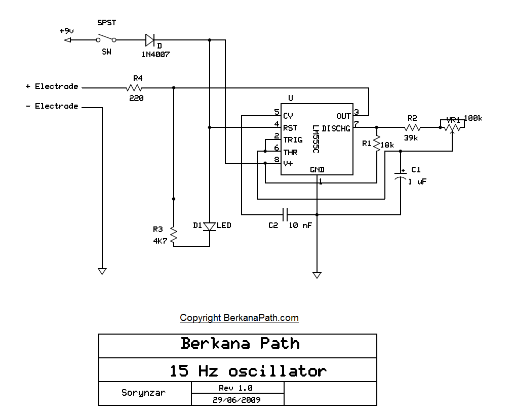
15Hz Zapper Schematic
I have uploaded my own personal schematic of a 15Hz zapper circuit. I spent some time trying to find a good schematic to follow last year, but I discovered that most of them were flawed and the timing formulas did not equate their components to being the correct 15Hz output. To remedy this, I drew my own schematic, built the circuit on a breadboard and tested the output using an oscilloscope. (Yes I test my circuits, unlike some armchair engineers) It is quite difficult to get an analogue circuit dead on 15Hz due to the poor tolerance of the components. The best tolerance you can get for this particular circuit components are 1% for the resistors and 2% for the capacitors. All of this considering, I managed to get the zapper circuit tuned to 15.15Hz using the variable resistor. Without the tuning, the circuit could output anywhere from 12-20Hz.
While this circuit is labelled as a zapper circuit it does not necessarily need to be used for that purpose. I originally used this circuit to pulse a scalar coil. I found that the circuit output, while o.k for zapper functionality has a very low power output for use with a coil. To remedy this issue, I have recently redesigned the circuit with a small power amplifier included, which significantly boosts the output from the coil.
Some other things for you to consider when using the zappers are the electrodes themselves. Instead of using two hand held copper electrodes, why not create a true anode and cathode by having a Zinc and a copper electrode? The results are quite interesting.
To view a larger image of the schematic, just click on the image, and it will take you to the full size drawing.
Related Blogs
- Related Blogs on 15Hz zapper circuit
- Related Blogs on hulda clarke
- THE HULDA CLARKE LIVER CLEANSE – A life Saver Nutech2000 Infopedia
- Dr Hulda Clark talks about Pollonium Clorox bleach Curing Cancer …
- eChic lifestyle blog » Blog Archive » The Liver Flush – One of the …
- Burzynski Clinic 30 Years Anniversary Gala
- Hulda Clark Parasite Zapper (Unofficial Based on Her Book Cure for …


Leave a Comment