How to Wind Toroidal Mobius Coils
This was an original post from Wizzers workshop before John Logan and his site disappeared. A couple of years ago I ask Mr.Logan if I could publish this particular info of his as I found it really useful when I first started making these coils. He gave me permission, so for all my readers here is the article.
an original coil design developed at Wizzers Workshop and the first such online tutorial anywhere on the web…
updated Sep. 2006
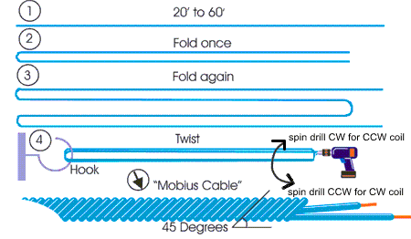
This coil is composed of a series quadrifilar cable with a 45 degree helical twist; the cable is then wound with a toroidal winding pattern. The first wrap of the cable serves as the core around which to wind the toroid. Realistically, it will seldom be a perfect 45 degrees if wound by hand. Angles between say 38 and 45 seem to work well enough but the closer to 45 the better.
First – Make yourself a “mobius Cable” to wind the coil from. While you can wind a mobius coil from single strands of wire, it certainly seems to be a lot more potent when you use a helical cable made in the manner described here to wind the coil from. Take a length of wire, and double it back on itself twice as shown to the right. Pull a little slack out at the ends of the wire, this will be the leads of the coil when it is finished. You should leave yourself at least 2″ for leads, and it is a good idea to give yourself 6″ or so, you can always trim the leads to the required length when the coil is finished. It is much easier to use a drill to twist the wires than doing it by hand. After experimenting with both CW and CCW coils, we have discovered that either will work. For many, a CCW coil is more comfortable. The way that the coil leads enter the drill is not detailed in the color image above, see the B&W image below for details.
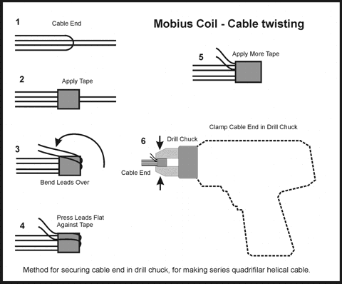
Shown in the second picture is a method to fit the cable end into the drill.Before inserting the cable end into the drill to twist it, fold the leads back so that they point towards the end of the cable opposite the end with the leads. Then wrap a few turns of electrical tape around the wires to protect them from the drill. Use about 5 or 6 turns of electrical tape. This provides a cushion so that when you tighten the drill chuck on the wires, it will not scrape off the insulation. While working with the coil, be careful not to scrape the insulation off the wires, or the coil will short out and not work. The thinner the wire, the more tape and the more gently you must operate the drill. Take care not to scrape the insulation off the wire while working with it. It is a good idea to wrap a few turn of electrical tape over the hook to cushion it, and replace the tape as it wears over time (if you make a lot of them). Visually inspect each cable for damage to the insulation. Lacquer-insulated ‘magnet wire’ works great in sizes larger than AWG 26, for sizes smaller than AWG 26 use plastic insulated wire.
Solid core wire is preferable IMO, but with sizes below AWG 26 or so you may need to use wire made from woven strands in order to avoid breaking the wire. It can be done (with magnet wire) but it’s not easy and the process would best be served by a wire winding machine and that’s out of the range of most tinkerer. So… If using very fine wire, then use wire with a plastic insulation and woven strands because this is physically stronger than the lacquer coated wire. It also occupies approximately 3 to 5 times the space for the same length of wire in a coil. Check each cable to verify that it connects electrically from end to end and that the wire is not broken inside the cable.
For a 60 foot cable made from 18 AWG, you should be able to measure ~ 0.5 Ohms resistance. If there is 0.0x ohms resistance and you have at least thirty feet of wire, you probably have a short. With thinner wires, the resistance increases. This page has detailed wire resistance per foot tables which i used to give the examples shown below. Determine how much resistance your cable should have and check it with a cheap digital multimeter if possible (this is only an issue if you are using really thin wire). Alternately, you could devise some other means to determine that the wire is not broken after twisting. Using a multimeter lets you both determine if the wire is broken or not and if it is shorted or not.
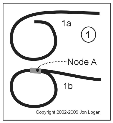
1. – Starting with the end of the cable which does not have the leads, make a circle in the cable about the size you want your finished coil to be. Wind the way that tightens the cable not the way that loosens it; you will see what this means when you get into it. You can wind the coil around a form initially if using stiff wire to form it. If using thin wire then you can make 2 or 3 wraps around the circle to stiffen it up a little. Make the circle just a little larger than you desired coil size. The spot where the circle closes is called Node A. Use a little glue (hot melt or silicone preferable) to hold the wire in place where it meets itself at Node A. You may wish to apply a little hot melt glue on the first pass around the circle, as you set the locations of the next three nodes.
Even better is to slide a short length of heat shrink tubing on the end of the cable before making circle. Then make the wrap, slide the heat shrink tubing over the joint and shrink it. You can only use heat shrink tubing on Node A. For Nodes B, C and D use hot melt glue or electrical tape. If the coil is small enough you may even be able to hold things in place by hand until it holds it’s own shape.
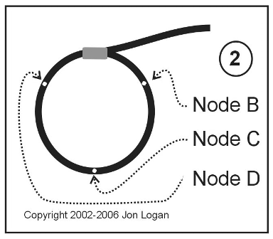
2. – Even out the circle, and mark off 3 spots arranged equally around (the circumference of) the circle. Note the names I have assigned them in the image.
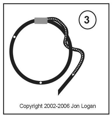
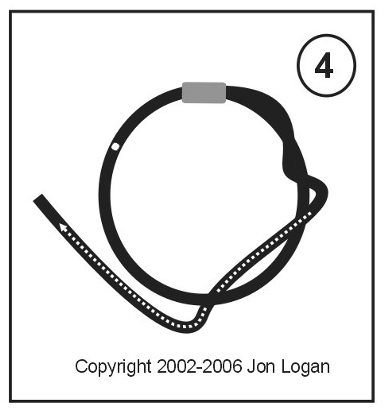
3. – Feed the other end of the cable (the end with the leads) through the hole in the center of the circle. Pull the length of the cable through the hole. At the spot where it crosses over itself, bend the cable around to the outside of the circle again, kind of like sewing a stitch. Make place where the cable wraps around itself at the spot marked as Node B in these images (the first of the 3 marked off spots you will come to as you continue around the circle from Node A.
4. – Do the same thing at Node C.
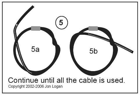
5. – Do the same thing again at Node D. Even out the placement of the nodes and adjust the cable so that the circle is reasonably uniform. Keep on ‘sewing’ your way around the circle until you have used all of the cable. Stay to one or the other side of the previous wrap as you go to keep the coil neat. The nodes will move to the side each time you add a layer, and eventually they will all run together. This method is suitable for cable lengths of up to about 20 feet. if you want to put more wire in the coil then the simplest way to do it is to make it a 6 or 8 filament cable instead of 4 and / or add several coils together.
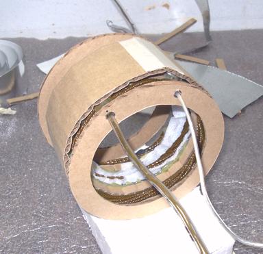
The coil should look something like this when you are finished. Use a little glue to hold the spot where the leads exit the coil securely. There are lots of pictures spread around the site which show many different examples of this type of coil.
Above example: QMD-S internal mobius coil
Just keep wrapping the cable around itself (clockwise) as you go around the circle. With a little practice, you will find that the windings form a pattern, and if you make a mistake it will be obvious as it does not fit the pattern. This coil tends to hold its shape reasonably well once you get it started. You should measure the diameter of the object you wish to place in the coil as a core when it is finished, and start with a circle a little larger than the diameter of the intended core.
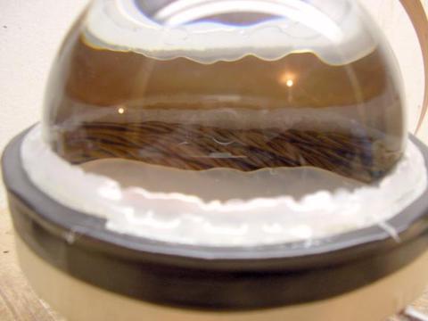
I recommend using a Quartz or Water-in-a-glass-vessel core for mobius coils, because scalar energy can sometimes be biologically disruptive when in ‘raw’ states. This information is primarily intended for those who wish to use mobius coils as a means of exciting Quartz crystals or Orgone Matrix Material, and you are responsible for your own safety. By making this coil you agree not to hold me responsible for any damages your experiments may cause to persons or property. Mobius coils generate scalar waves. Scalar waves can sometimes interfere with and/or damage electronics when produced at high power levels. For the purposes of Orgone research, power levels in the range of 0.5 to 50 watts are more than adequate.
The coils are also partially active with no electrical power supplied in that they tend to attenuate scalar background energy. They are least active when the coil leads are isolated and most active (without power supplied to them) when the leads are shorted together. When using these coils in radionic devices a purge function may be applied by momentarily connecting the coil leads to each each other and / or ground. This is not always necessary but mentioned for posterity.
<- example: ViBR III.2.x internal coil assembly
Simple and even messy-looking coils will still produce usable simple SP devices; the angle of the cable twist is of more importance than the neatness of the toroidal windings. Nodes will tend to form in the able and do not impair function of the coils for this level of application. Further refinements to the coils which are possible for the experimenter are the geometrical and size relationships of multiple coils to each other for combined action, mirror image sets of coils arranged in bucking 180 or 90 degree rotational offset but on the same plane,45 degree planar offset of two coils aligned on common axis (credit to L. White), dowsing or mathematical determinations of exact cable wire length. I leave it to you to determine what effects these modifications generate; the basic coil form depicted here is the simplest and most functional in terms of labor in to perceptible field effect out.
Again, for simple scalar field modulators to be used in radionics or small wands such the SP type of device … the coil does not need to look pretty. It needs to have the cable twisted up to an angle approaching 45 degrees through most of the cable length and to have it wrapped back though the center of the circle in a toroidal pattern.
This is the archive link to Little Mountain Smudge/ Wizzers Workshop. The website is no longer with us, but John Logan provided a great deal of info when it was running.




Leave a Comment